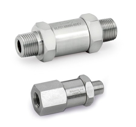
Micron In-ine Filters : Series - MLF01
FEATURES
- Available in SS316
- Heat Code Traceable to certified material test report
- Remove system particulate contaminants
- Inline Filters are for use where space is limited
- Replaceable filter elements
- Variety of end configurations includes SEALEXCEL® Well-Lok™ Tube Fittings, Male/Female NPT, BSPT and BSPP pipe connection

OPERATING PARAMETERS
- Pressure Rating : upto 3000 psig (206 bar) at CWP
- Temperature Rating : -28ºC to 482ºC
TEMPERATURE AND PRESSURE RATING
| Material | SS 316 | |
| Orifice Size | 2.4mm & 4.8mm | 7.1mm & 10.4mm |
| Temperature F( C) | Working pressure psig(bar) | |
| -20(-28) to 100(37) | 3000(204) | 2500(172) |
| 200(93) | 2580(176) | 2150(148) |
| 300(148) | 2330(160) | 1940(133) |
| 400(204) | 2140(147) | 1780(122) |
| 500(260) | 1990(137) | 1660(114) |
| 600(315) | 1880(129) | 1560(107) |
| 650(343) | 1845(127) | 1540(106) |
| 700(371) | 1800(124) | 1500(103) |
| 750(396) | 1760(121) | 1460(100) |
| 800(426) | 1725(118) | 1440(99.2) |
| 850(454) | 1690(116) | 1410(97.1) |
| 900(482) | 1640(112) | 1360(93.7) |
EFFECTIVE FILTRATION AREA
| Orifice Size mm | Effective Filtration Area in (mm ) Sintered |
| 2.4 | 0.55(350) |
| 4.8 | 1.3(830) |
| 7.1 & 10.4 | 2.0(1280) |
FILTER ELEMENTS
| Nominal Pore Size µm | Pore Size Range µm |
| 0.5 | 0.5 to 2 |
| 2 | 1 to 4 |
| 7 | 5 to 10 |
| 15 | 11 to 25 |
| 60 | 50 to 75 |
| 90 | 75 to 100 |
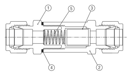
MATERIAL OF CONSTRUCTIONS
| No. | Component | Material |
| 1 | Inlet Body | SS316 |
| 2 | Outlet Body | SS316 |
| 3 | Filter Elements | SS316-Sintered |
| 4 | Gasket | Silver Plated SS316 |
| 5 | Spring | SS34 |

FLOW DATA AT 70ºF (20ºC)
| Nominal Element Pore Size mm | Inlet Pressure psig(bar) | Pressure Drop psig (bar) | ||||||||||||||||
| 5 (0.34) | 10(0.68) | 15(1.0) | 10(0.68) | 50(3.4) | 100(6.8) | |||||||||||||
| 2.4 | 4.8 | 7.1,10.4 | 2.4 | 4.8 | 7.1,10.4 | 2.4 | 4.8 | 7.1,10.4 | 2.4 | 4.8 | 7.1,10.4 | 2.4 | 4.8 | 7.1,10.4 | 2.4 | 4.8 | 7.1,10.4 | |
| Air Flow, ft /min | Water Flow, ft /min | |||||||||||||||||
| 0.5 | 0.04 | 0.12 | 0.36 | 0.06 | 0.26 | 0.86 | 0.12 | 0.48 | 1.6 | 0.001 | 0.005 | 0.012 | 0.005 | 0.023 | 0.053 | 0.016 | 0.039 | 0.102 |
| 2 | 0.20 | 0.6 | 1.4 | 0.40 | 1.4 | 2.8 | 0.60 | 2.3 | 4.0 | 0.01 | 0.032 | 0.035 | 0.032 | 0.115 | 0.147 | 0.053 | 0.174 | 0.214 |
| 7 | 0.50 | 1.4 | 1.8 | 0.90 | 2.9 | 4.2 | 1.2 | 4.7 | 6.8 | 0.013 | 0.053 | 0.086 | 0.04 | 0.174 | 0.294 | 0.064 | 0.267 | 0.468 |
| 15 | 0.80 | 1.2 | 1.8 | 1.3 | 2.9 | 4.9 | 1.5 | 4.7 | 7.9 | 0.016 | 0.067 | 0.112 | 0.048 | 0.174 | 0.348 | 0.078 | 0.28 | 0.548 |
| 60 | 1.7 | 3.1 | 5.1 | 2.2 | 5.9 | 10 | 2.4 | 8.5 | 15 | 0.02 | 0.12 | 0.267 | 0.067 | 0.441 | 0.896 | 0.094 | 0.615 | 1.337 |
| 90 | 1.8 | 4.0 | 6.1 | 2.2 | 7.5 | 11 | 2.6 | 10 | 16 | 0.027 | 0.16 | 0.307 | 0.067 | 0.561 | 1.02 | 0.08 | 0.815 | 1.47 |

STANDARD CONFIGURATION DIMENSIONS
| End Connections | Orifice (mm) | Dimensions mm | Ordering Number | |||
| Inlet | Outlet | H | I | L | ||
| 1/8" Well-Lok | 2.4 | 14.3 | 29.2 | 59.7 | MLF01-TT2 | |
| 1/4" Well-Lok | 4.8 | 19.0 | 39.7 | 75.2 | MLF01-TT4 | |
| 3/8" Well-Lok | 7.1 | 25.4 | 43.2 | 81.8 | MLF01-TT6 | |
| 1/2" Well-Lok | 10.4 | 25.4 | 43.2 | 86.9 | MLF01-TT8 | |
| 3mm Well-Lok | 2.4 | 14.3 | 29.2 | 60.5 | MLF01-TT3M | |
| 6mm Well-Lok | 4.8 | 19.0 | 39.7 | 75.2 | MLF01-TT6M | |
| 10mm Well-Lok | 10.4 | 25.4 | 43.2 | 82.2 | MLF01-TT10M | |
| 1/8" Male NPT | 2.4 | 14.3 | 29.2 | 48.6 | MLF01-MM2N | |
| 1/4" Male NPT | 4.8 | 19.0 | 39.7 | 68.3 | MLF01-MM4N | |
| 3/8" Male NPT | 7.1 | 25.4 | 43.2 | 71.6 | MLF01-MM6N | |
| 1/8" Female NPT | 2.4 | 14.3 | 29.2 | 54.9 | MLF01-FF2N | |
| 1/4" Female NPT | 4.8 | 19.0 | 39.7 | 72.9 | MLF01-FF4N | |
| 3/8" Female NPT | 7.1 | 25.4 | 43.2 | 77.2 | MLF01-FF6N | |
Dimensions are for reference only and are subject to change without Notice
